The miniSMU MS01 features a compact and functional design, optimised for computer-controlled operation. This section provides a detailed overview of the physical layout and controls of the device to help you become familiar with its features.
Front Panel
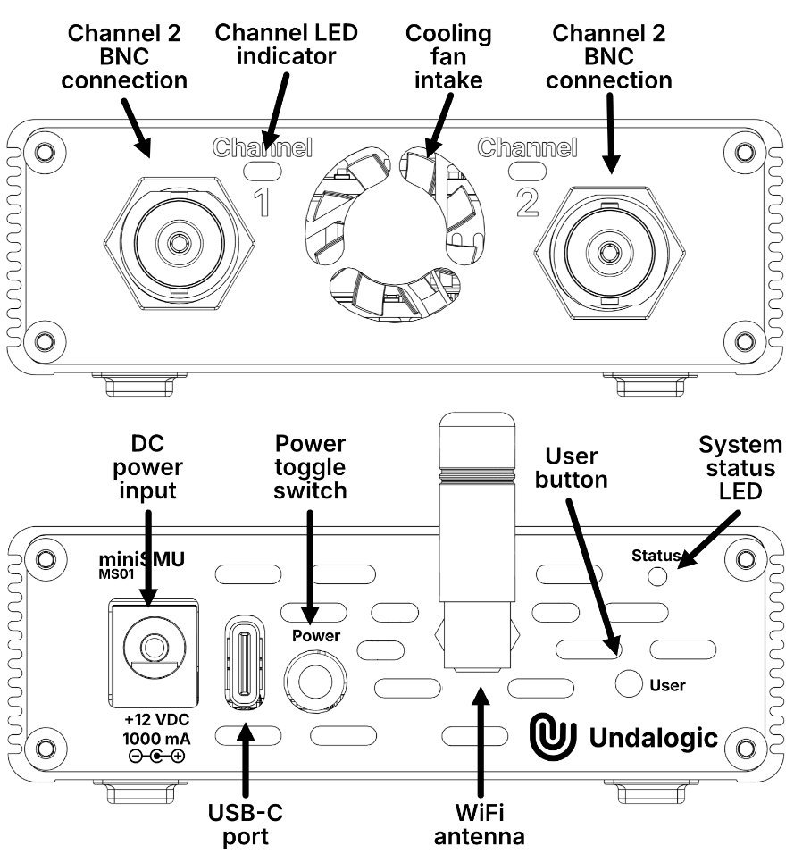
The front panel of the miniSMU MS01 houses the main measurement connections and status indicators:
Channel Connections
- Channel 1 BNC connector - Primary connection for Channel 1 measurements
- Channel 2 BNC connector - Primary connection for Channel 2 measurements
The BNC connectors provide a secure and reliable connection for your measurement leads. The center pin carries the signal, while the outer shield serves as the reference ground.
Status Indicators
- Status LED for Channel 1 - Indicates the operational status of Channel 1
- Status LED for Channel 2 - Indicates the operational status of Channel 2
The status LEDs provide at-a-glance information about the operation of each channel. See the Indicators and Controls section for detailed information about LED status indications.
Cooling System
- Intake for cooling fan - Allows airflow for thermal management
The cooling intake should be kept clear of obstructions to ensure proper airflow and prevent overheating during operation.
Rear Panel
The rear panel contains all the connectivity, power, and control interfaces:
Power Connections
- 12V DC barrel connector (Center pin positive) - For connecting the included AC power adapter
- USB-C port (USB 2.0) - For both computer connectivity and optional power (with limited current capability)
Controls
- Power on/off toggle switch - Main power control for the device
- User button - Multifunctional button for WiFi control and other operations
Connectivity
- SMA antenna connector for WiFi - Connection point for the included WiFi antenna
Ventilation
- Cooling fan exhaust slots - Exit point for cooling airflow
Ensure that both the intake vents on the front panel and the exhaust slots on the rear panel remain unobstructed for proper cooling.
Bottom View
The bottom of the device includes:
- Rubber feet - For stable positioning and shock absorption
- Product label - Contains serial number, regulatory information, and power specifications
Physical Design Considerations
The miniSMU MS01 is designed with several key physical attributes:
- Compact footprint - 137mm x 82mm x 29mm (including WiFi antenna)
- Lightweight construction - Weighs only 225g
- Durable enclosure - Protects internal components while dissipating heat
- Portable form factor - Easy to transport between workstations or to field testing locations
Connection Guidelines
When connecting cables to your miniSMU MS01:
- Ensure that connectors are properly aligned before applying pressure
- Avoid forcing connectors which may damage the ports
- Provide strain relief for cables to prevent damage to connectors during use
- Keep cables organised to prevent accidental disconnection
Understanding the physical layout of your miniSMU MS01 will help you operate it efficiently and maintain it properly. For more detailed information about the status indicators and controls, please refer to the next section.